In my journey, in FTC I learned many things and came across many different challenges. I had to overcome all of these challenges and I learnt a lot in the process.
One of the major things that I learnt was 3d designing. Before I had some minor knowledge of using Fusion 360 but I learnt a lot more during this competition. As the only 3d Designer in the team I had to design many of the major parts we needed for the competition. Here are a few of the things that I designed.
Battery Holder
To hold the battery to our robot, we needed a holder to store it and help us attach it to the robot. To start, I took the battery measurements by the scale and created a sketch to be the base, then extruded the walls and the base.
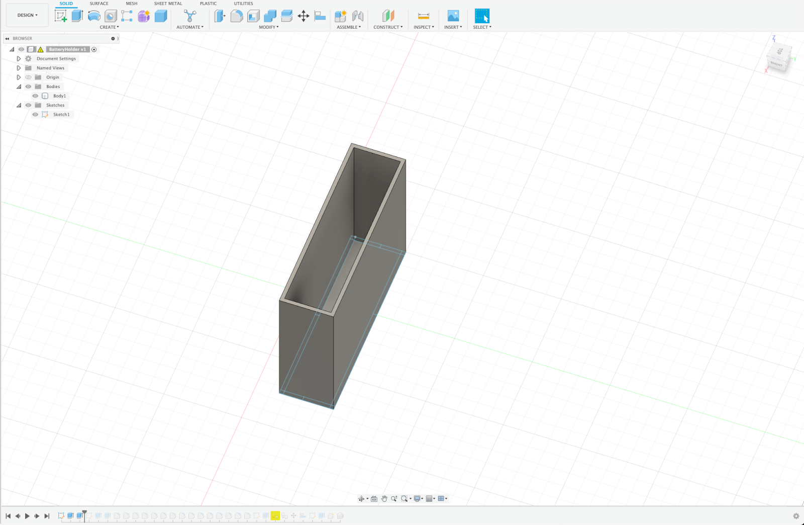
I made a slot for the wire of the battery to be able to come out.

With the rough design of the battery holder down, I started the refinement of the build and filleted down all the sharp edges. However, if I were to re-design this part, I could count this step as a mistake as I have learnt that I should fillet the design at the very end since it becomes easier to edit the part.
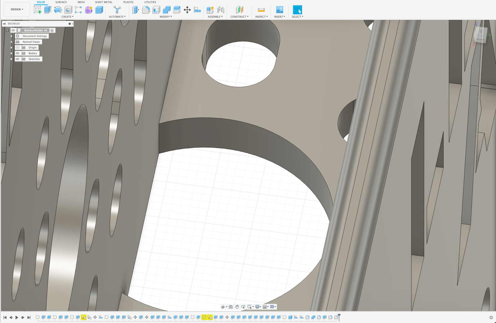
I needed the holes based on the goBILDA pattern to attach the battery to my robot, so I took the step file of the 3-hole plate from the goBILDA website. I made a slit on the side of the battery holder according to its size and placed it in the slit.
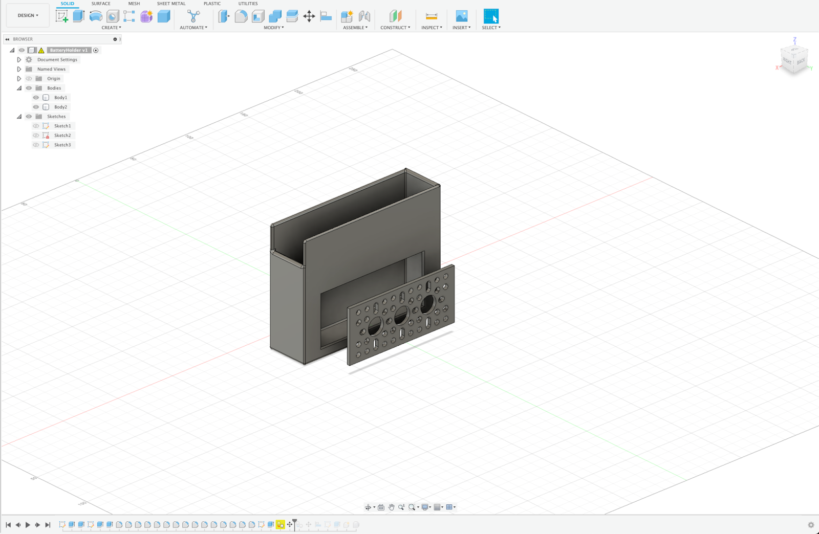
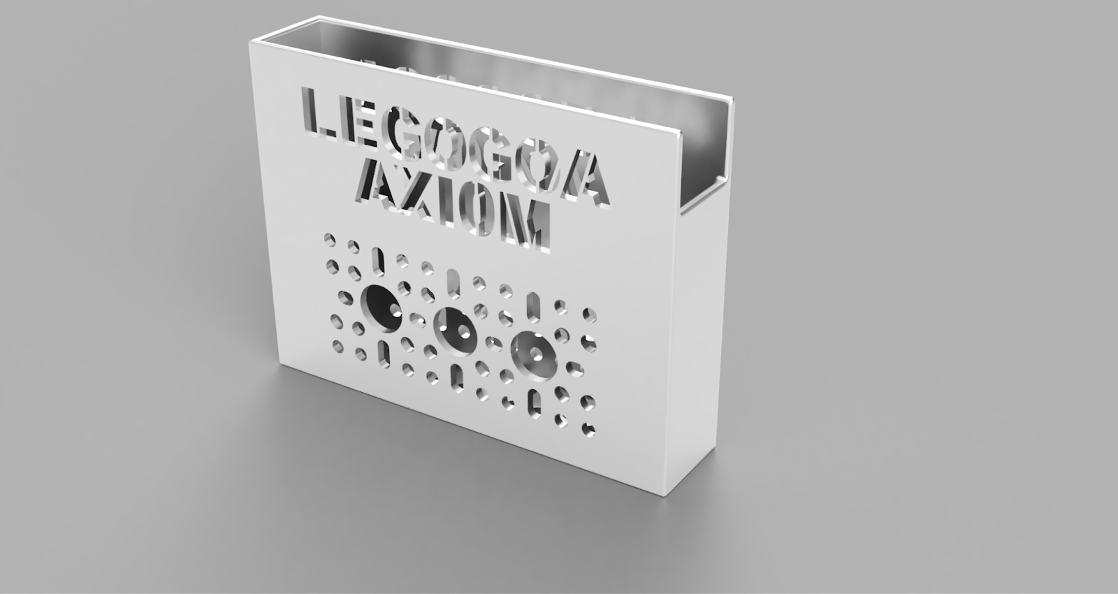
I did the same for the other side and put our name on the side of the battery holder.

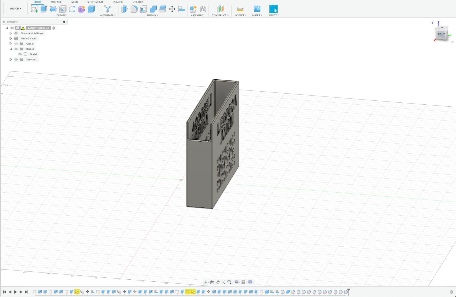
While putting our name on the battery holder, I realised that I couldn’t use a standard font as the inside of the letters would fall out, so I installed a 3D font and used that to put my name on the part.

I then put another plate on the bottom for maximum connection points. To do this, I first cut the side of the container to make it fit in the base and then, like before, made a slit and put the plate there.
Thus the first version of my battery holder was completed, and I sent it for printing.

I realized that the battery holder was slightly wider than the battery, so I had to make it smaller. I was not very experienced with editing then, so I had many issues. First, since I didn't know about the timeline and how to use it then, I used a highly complex method to make it smaller. If I had to do it now, it would take barely 5 minutes since I could use the timeline to modify the original sketch and then modify the remaining features. But instead, at that time, I tried extruding the walls. I had to delete all the fillets. I made and then extruded the wall to match the bottom plate. I had to take it back out and remove more of it to fit. Also, in the previous model, the base plate had been too thin and didn't print, so I fixed that issue.
I also discovered that the plate was slightly extruding out in one place in our old design. I promptly fixed this. And thus, the second model of my battery holder was completed.
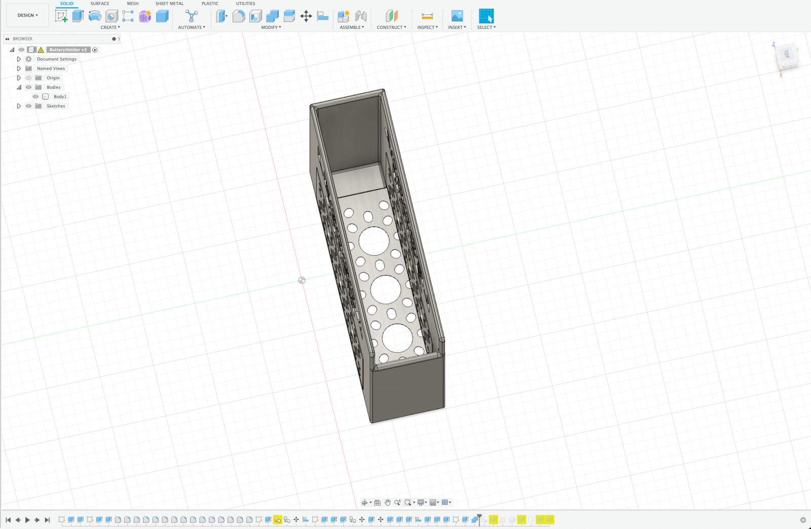
For Battery Holder Version 3, I realized that the bottom plate of my design was pretty messed up due to my inexperience.
To fix this, I remade the entire bottom and made it proper.

With this, my entire battery holder was completed, and I could use it correctly in our robot and still use it to hold the battery.
Gear Rack
For the gear rack, we wanted our claw to be able to come out to grab the cones from a distance. To do this, we used a slider to extend the claw. we originally planned to use a thread and the standard method to extend the slider. we realized, however, that it would be too complicated to put two motors. So we instead came up with the idea of using a gear rack and pinion to extend it.
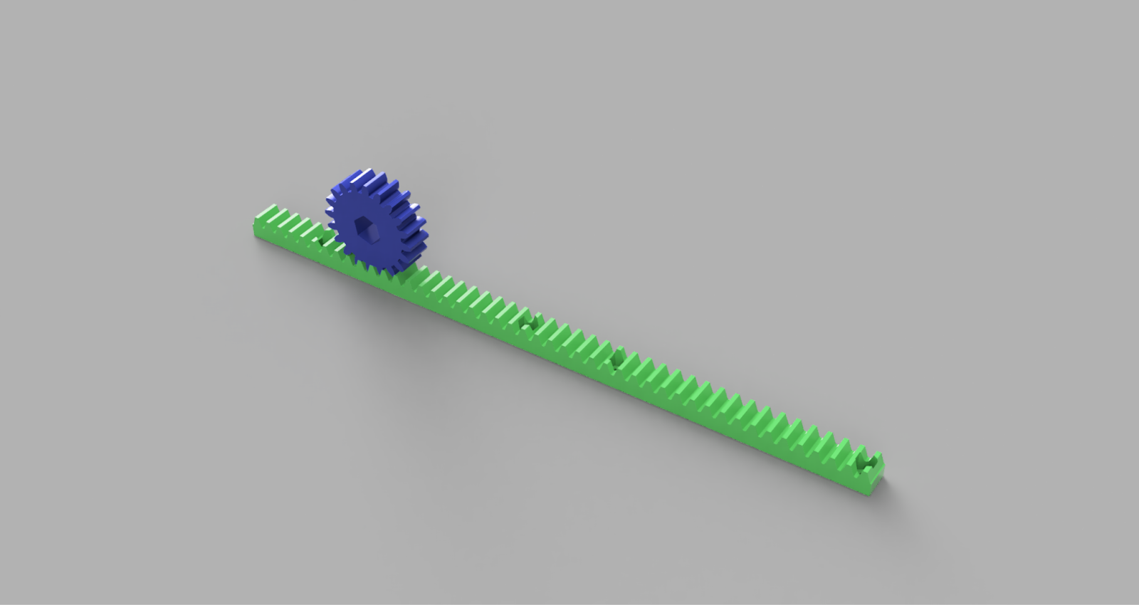
For the first version of the gear rack, I downloaded and modified a rack and pinion mechanism from the internet, made it to the sizes I needed according to the goBILDA viper slider

and made the gear hole according to the REV shaft. I put holes in the gear rack to connect it to the slider and set places for the nuts to place the nut in the rack and then put the screw through from the slider.
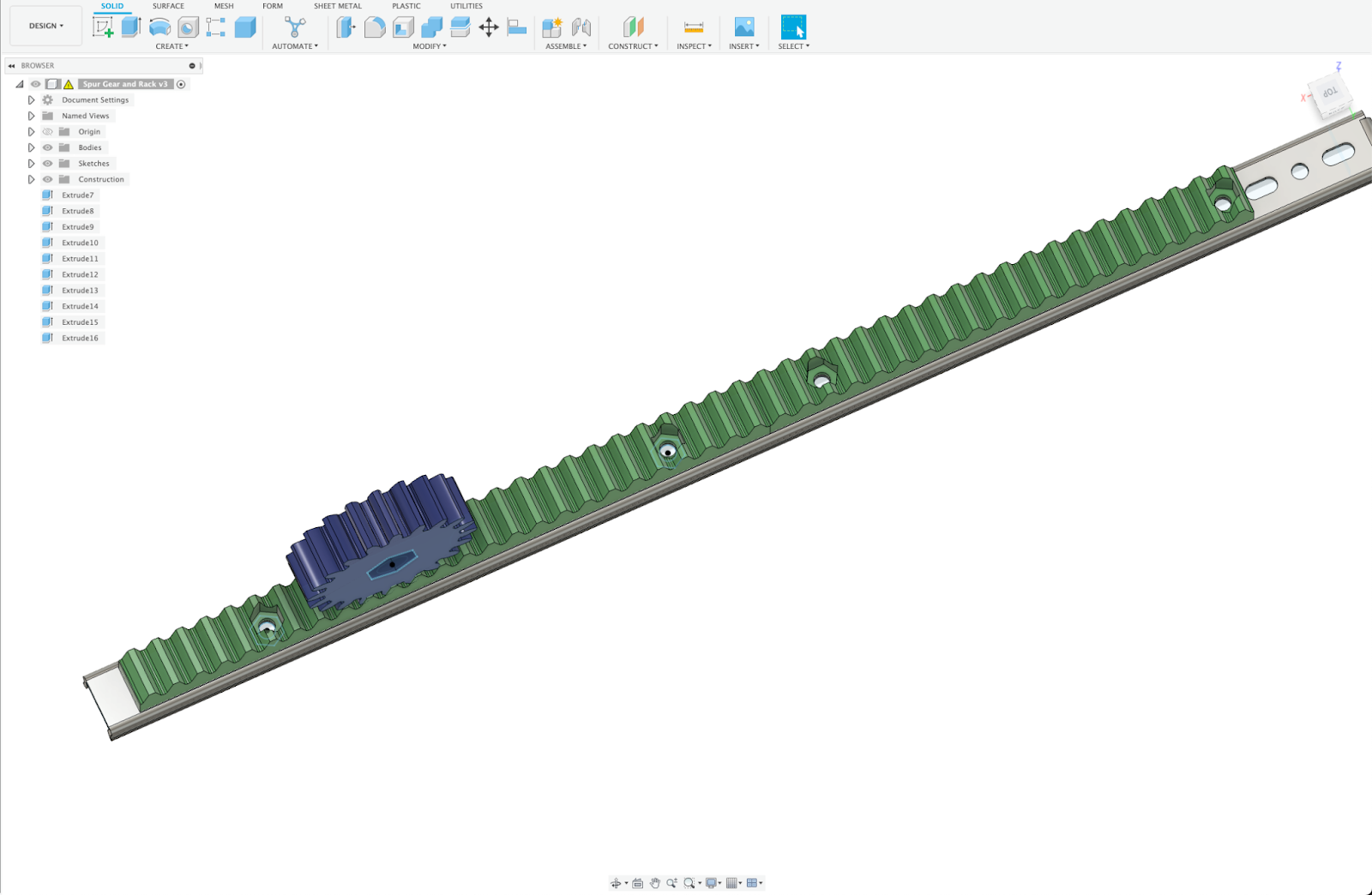
In subsequent versions, I made minor changes, such as adding four holes for the gear to connect better to the REV shaft and changing the gear rack style from standard to herringbone. In the herringbone design we realized that we could not make hotels for nuts and had to use a 2 compound glue.

For the second version of the gear rack, I realized that the gear rack was too slow and that I needed to make it faster. To do this, I made the gear twice as big and tried to see if it worked. However, this did not make it fast enough, so I came up with the idea of connecting the big gear to the motor and putting a small gear in between the gear and the gear rack to make it even faster. However, to make such a connection, I needed to design my mounting plate for the motor, which would also provide the holes for the gears. To create such a plate, I took the exact measurements and made the connection part precisely like the goBILDA U channel where I would connect this. I also made precise holes for my core hex motor to fit. And thus, my Gear rack was completed.

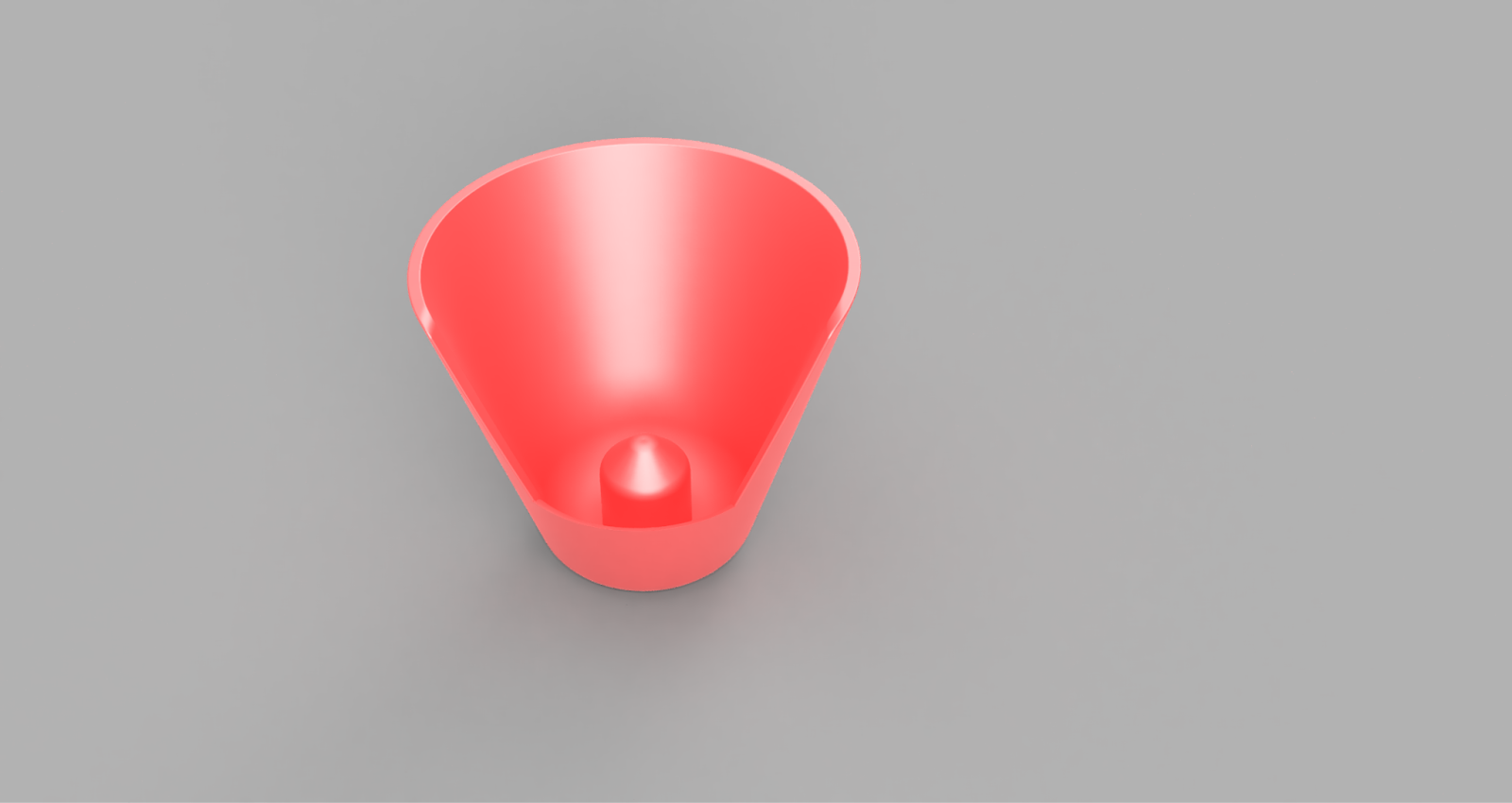
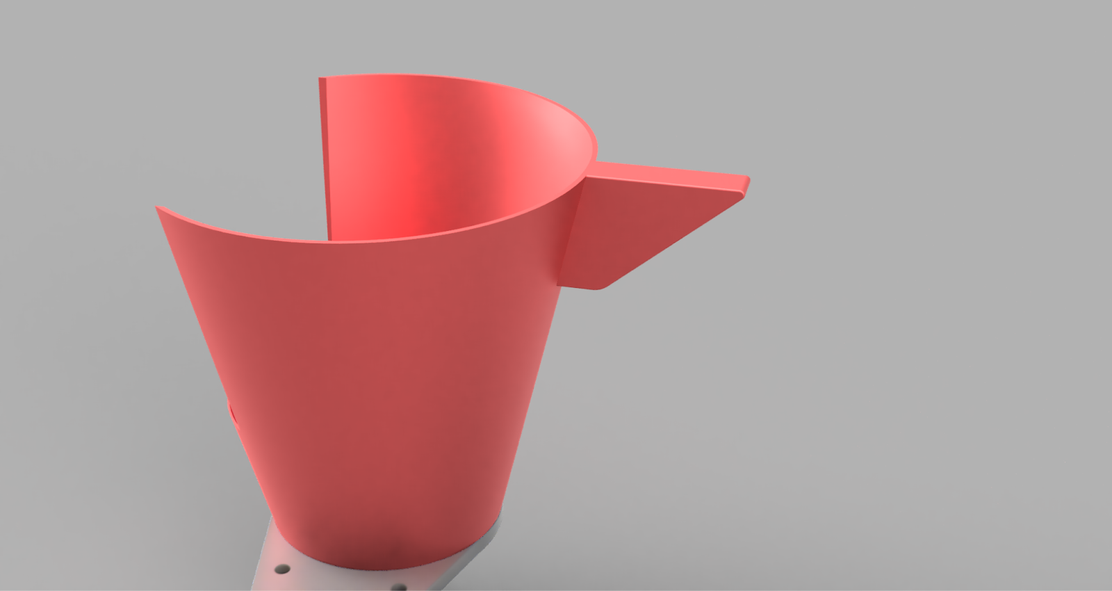
Cone Holder:
We needed a properly designed holder so that we could properly hold the cone, and it needed to be in such a way that no matter how the claw dropped the cone, it would still land upright in the cone holder..
Cone Holder Version 1
To make the base of the cone holder I took the measurements of the cone and made a rough shape of the cone holder. I made sure that near the top, the holder was a lot wider than the cone so that it could receive the cone from any angle. I added a little bump near the bottom to align the cone into the holder properly. I also added an elongated stick that could directly connect to my servo motor for me to move the cone holder.


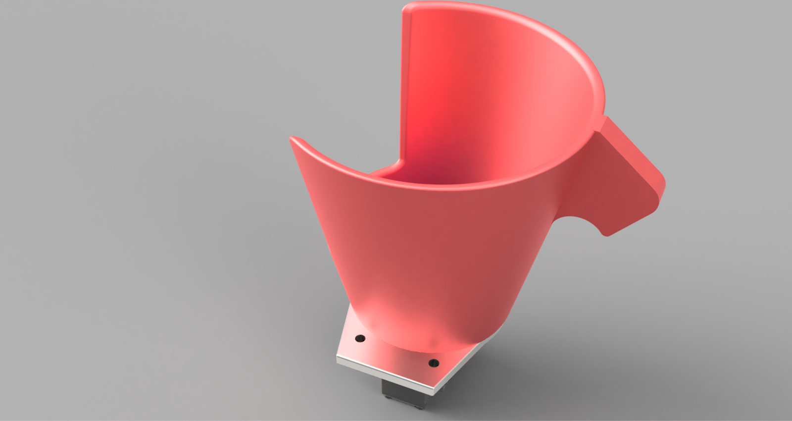
Cone Holder Version 2
The problem with this design was that the cone holder was a bit too big and the cone could slip around inside it. So I made the cone holder a bit smaller and changed the inner bump from a round tip to a conical shape. I also removed the connecting stick and instead burnt through holes for screws near the top.
Claw Holder version 3:
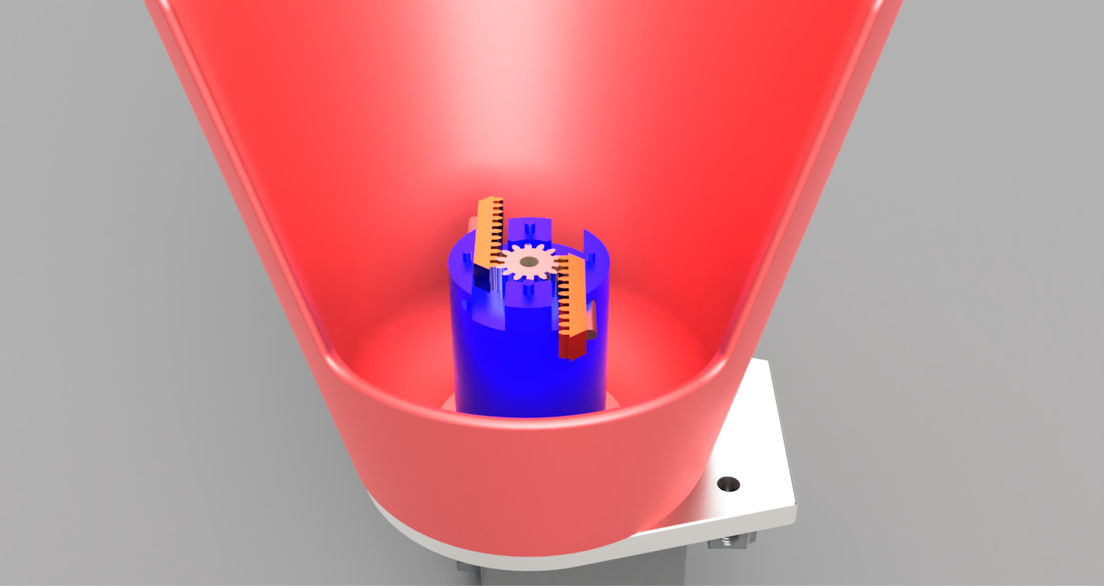
Now I realized I needed an active locking mechanism powered by a servo which would hold the cone in place so that even when I made the cone holder upside down, the cone would remain in place and then I could navigate to the junction and then release the cone. To do this, I first considered having an arm near the outside of the cone holder which would then push the cone inward. But after thinking for a while, I came up with the genius idea of having the positional bump be taller and then extending a mechanism into the cone. I then had to think of what mechanism I could use which would be so small but still be able to extend properly. My first idea was to use a gear rack and gear on the inside which when spun would extend out and into the cone.
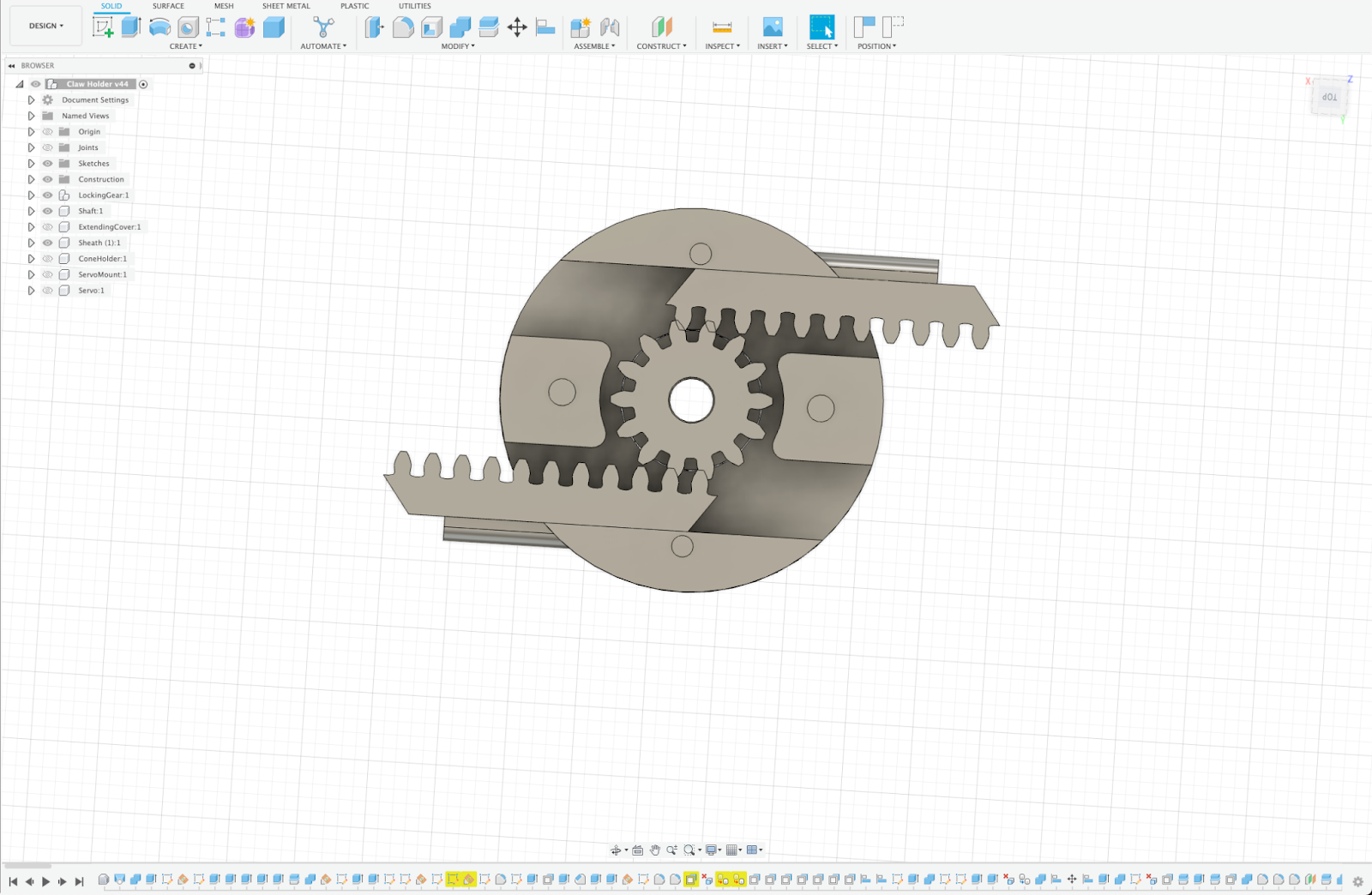
I thought that this was however too flimsy and the gear rack would bend, and the cone would fall out. So I started thinking of something else. Then I got the idea of using a gear in the centre and two smaller wings on the side which would extend out and block the cone. I decided to go through with this design.

First, I needed to figure out a way to connect the servo to the cone holder. To do this, I made a small plate near the bottom to which I could attach the servo.

I made the inner part of the inside bump a shaft with teeth to match the servo near the bottom.
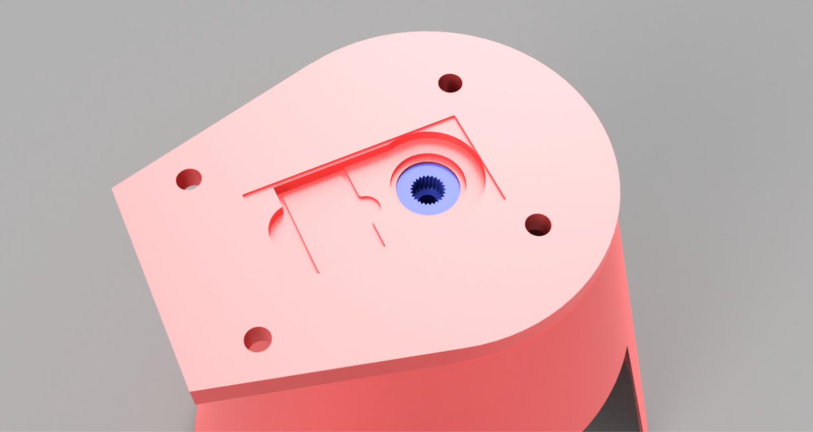
Then I mounted the central gear on the shaft, made pins for the wings, and designed the wings. I also made the cover near the top. I ensured that a hole was running through everything so I could put a screw through it and into the servo. I also made a depression near the top so that the screw head would not interfere with the cone. For the mounting of the cone holder to the robot, I also needed a new system as I needed to mount the cone holder at an angle from the beam, so to accomplish that, I made an extension near the back.
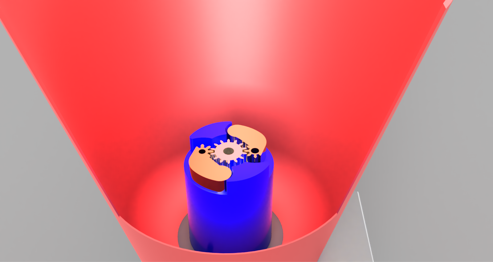

Claw Holder Version 5
While using the locking mechanism for a while I realized that the gears were breaking. I replaced the gears several times but the small gears of the wings kept breaking. Thus I realized that this mechanism was wrong and I couldn’t use it with small and fragile gears. So I decided to revert to my old design and started making that. I made the gear racks according to the teeth of the gear and I made a small bump on the gear rack to align it.
I then implemented this design and made other slight modifications such as the connection point, the thickness, the edges etc.


Comments
Post a Comment